

How Doi Return To The Drawing Screen In Solidworks 2018
Having taught SOLIDWORKS for over sixteen years, I have accumulated many best practices and drawing tips that I regularly share with my students. In this article, I will share these with you in the hope that they will assist you lot produce better drawings more than quickly.
A SOLIDWORKS drawing can be broken into two major components. In that location is the drawing, which is often the last product of your blueprint, and there is the drawing template, which is the base of operations of all your drawings.
Drawing Templates
Because it is the base of your drawings, the importance of the drawing template cannot be overstated. Having a well-laid-out cartoon template tin can ensure that cartoon standards are existence adhered to and that there is a clear catamenia of data from document to certificate.
The drawing template is composed of iv major components:
- The template itself, which is the container for all the other components
- The document properties, which are used to define the drawing standards
- The sheet format, which is the area where we define our title block, canvas borders equally well drawing zones
- The sail backdrop, where nosotros define the sheet scale, blazon of project, likewise equally the canvass format
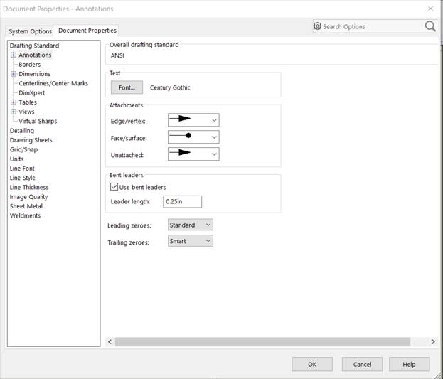
Document Properties and Drawing Standards
 The Document Properties window.
Let's commencement wait at the document properties. My offset tip here is to make use of the Certificate Backdrop dialog. Information technology surprises me how many times I see people use the default SOLIDWORKS Drawing Template and modify the document properties on the wing. Not merely does this create additional work, only this do inevitably leads to inconsistency between drawings.
The software ships with several drafting standards.
 Drawing standards in SOLIDWORKS.
You tin can tweak or completely modify these standards to come across your visitor's own standards. One time you lot have developed your standard, you lot tin can save it.
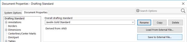 Saving a drawing standard.
Saving the drawing standards you created allows you to reuse them and can safeguard confronting the loss of your work.
Sail Format
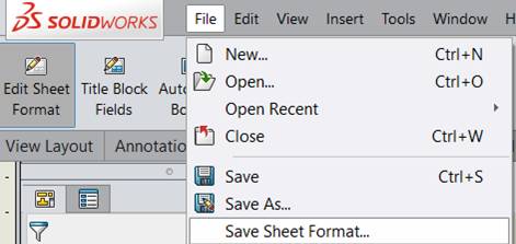
As mentioned earlier, the sheet format is where you define your championship block. A well-divers championship block will be aesthetically pleasing and pull existing data directly from the cartoon, or from the referenced model or assembly. The sheet format can exist accessed by right-clicking on a bare area of your cartoon and selecting Edit Sheet Format.
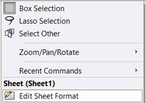 The Edit Sheet Format selection.
1 manner to corroborate the advent of your championship block is to have the annotations centered in a region of the title block. This is accomplished by right-clicking on an annotation, selecting Snap to Rectangle Center and so selecting the lines that define the borders of the rectangle.
 The Snap to Rectangle Heart choice.
To ensure that your championship cake displays the correct information, it is best to have a central repository for this information and then link annotations in the championship cake to this repository. This data is typically stored in the document backdrop of a cartoon, or in the referenced role or associates. To link an annotation to a property, start creating a annotation. Do not enter whatever text; instead, select Link to Property from the SOLIDWORKS Property Director.
 Linking to document backdrop.
In the Link to Property dialog box, select which document and document properties yous want to adhere your note to.
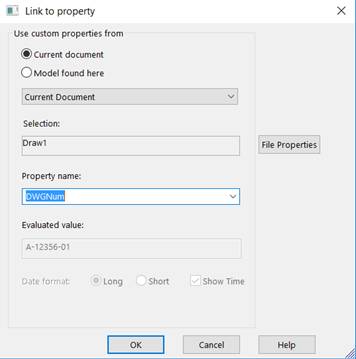 The Link to Property dialog box.
Linking annotations to properties can be practical to all annotations in your drawing, not just those in the title block.
Drawings edge sizes and drawings zones can exist created using automatic borders. Automatic borders can be accessed from the Sail Format tab of the Command Manager.
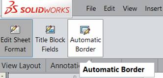 The Sail Format tab.
The Automatic Border tool is a multipage wizard that allows you to define your drawing borders and establish drawings zones. Once yous take established these zones, the zone information can then be added to a note from the Add Zone choice of the Property Manager.
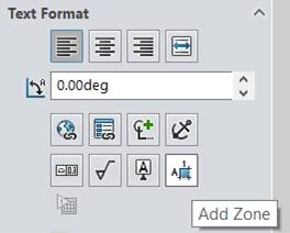 The Add Zone option.
Y'all can display the zone or just the zone column or zone row values.
 The Add Zone dialog box.
Once y'all have finished modifying the canvas format, yous can salve information technology to the drawing template after the template has been saved. You tin also save the sheet format equally a separate file for later employ.
 Saving a canvass format.
Sail Backdrop
 Sheet backdrop.
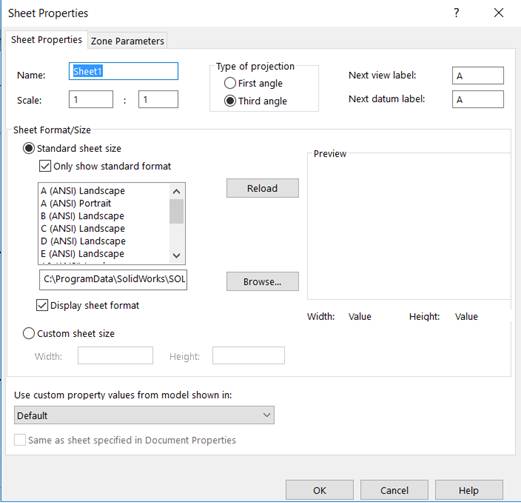
When information technology comes to sheet properties, in that location are ii tips I volition offer. The start is to ensure that the right canvas format is being used. If you spent all that time creating your sheet format, ensure that it is the 1 listed in the sheet properties. The 2nd tip is to continue in mind that you can switch the sheet size if you run out of room in your drawing. Canvas properties can be accessed by right-clicking on a blank area of your drawing and selecting Properties.
 Accessing canvass properties.
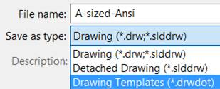
Saving the Template
One time you accept modified all the areas of the cartoon template, you will need to save all your piece of work. To exercise this, select Save As from the File pull-downwards carte in SOLIDWORKS. In the Save Equally dialog box, select Drawing Templates from the Save as blazon pull-down carte.
 Saving the cartoon template.
File Locations
To ensure that all SOLIDWORKS users in a visitor are accessing the same document templates and sail formats, these should be stored on a mutual network drive. Next, the file locations for each user's reckoner should be modified and then that they await to this mutual location. File locations are ready from Tools>Options>Organisation Options>File Locations. File locations, as well every bit other user settings, tin can exist copied using the Copy Settings Wizard. The saved settings from the Copy Settings Sorcerer can then be included in a SOLIDWORKS installation Admin Image so that these file locations are set up when the software is installed.
The Drawing
One Component, One Drawing
Whether information technology is a function or an assembly, the process of tracking which drawing is associated with which model or associates is greatly simplified by having one component as the focus of that drawing. Often I meet drawings that contain the chief-level assembly, all the subassemblies and all the parts in 1 drawing, with each component being represented in its ain sheet.
This may initially seem to be a smart way of enveloping an entire projection in one file, but what if some of these components are used elsewhere? Do we and so create a new drawing with its own hierarchy of sheets? Obviously, this would result in multiple drawings of the same components. How do we so identify which cartoon needs to be sent downstream of the design process? Which is correctly annotated? In fact, how practise we observe this one canvas that is buried in a drawing somewhere?
By having a simple relationship of 1 component and one cartoon, it is like shooting fish in a barrel to track the drawing and its referenced components. This tin be especially useful when working in a multiuser environment, or one where data direction software is used. If the cartoon needs to be accessed, you can exercise this directly from the open up, referenced part or assembly. This is done past right-clicking on the file name inside the Characteristic Managing director and selecting Open Drawing.
 Open Cartoon from Part.
Operation
Operation can always be a challenge with drawings. Not only tin big assembly drawings taxation your CPU and swallow RAM, just all the line work in a drawing tin also overload your video card. While you tin can become out and purchase a more capable system, there are things you can exercise to address this without having to spend your money on a new calculator.
The first affair yous tin exercise is to work from your local bulldoze. While network drives can be fast, they exercise not approach the functioning of virtually computers. If y'all demand to have these files accessible to multiple people, look for a data management solution. With these solutions, yous work from your difficult bulldoze, but yous tin bank check your work into a centralized location, so that others tin access information technology.
When opening a multi-canvass cartoon, y'all tin cull which sheets to load. This volition reduce open, rebuild and save times. This option is available from Open dialog box.
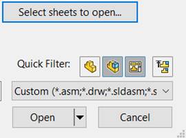 Selecting sheets to open.
Large Assembly Style tin increment performance past reducing the amount of information that is beingness loaded when you open up a drawing. This can also reduce open up, rebuild and salve times. Large Assembly Style can be enabled from Tools>Options>System Options>Assemblies.
Detached drawings can increase functioning by disassociating the drawing from its referenced component. With a detached cartoon, you can still create derived cartoon view and add dimensions and notes. A detached cartoon can be created from the Save Equally dialog box.
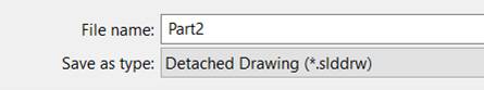 Saving a detached drawing.
Drawing Views
In some cases, it can exist easier to create a cartoon view in the model or assembly. This view can be saved and after inserted into a drawing. Drawing views are created in the View Orientation dialog box. 1 way to access this tool is by pressing the space bar on your computer keyboard.
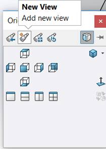 Creating a new view.
The newly created views will announced in the View Pallet of the software's Task pane.
Some other way of achieving the orientation you desire is to use the Relative View tool. This is available from the drawing and allows you to orient your view past selecting model geometry. This tool will too let you to isolate a body in a multiple-trunk part, such as a weldment.
If you create an auxiliary view that is tilted, yous can fix the alignment by right-clicking on the view and selecting Marshal Cartoon View.
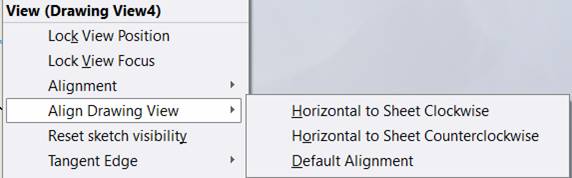 The Align Drawing View pick.
Checking Your Drawing
The Pattern Checker might exist 1 of the nearly underused tools in the SOLIDWORKS suite, but it can be invaluable in communicable variances from your drawing standards. The Design Checker is bachelor from the Evaluate tab of the Command Managing director. At that place are tools to build your checks, which tin can exist run on drawings as well as other document types. Design Checker is only available with SOLIDWORKS Professional and Premium.
In Closing
In this article, I take covered some of my favorite tips and best practices. I encourage you try these. I am confident that they will help y'all to create more robust and efficient drawings.
For more tips on drawings, visit the SOLIDWORKS website.
About the Writer

Joe Medeiros is a Senior Applications Engineer at Javelin Technologies, a SOLIDWORKS reseller servicing customers throughout Canada. Joe has been involved with SOLIDWORKS since 1996. An award-winning blogger, he regularly writes nearly SOLIDWORKS products.

Source: https://www.engineersrule.com/top-9-favorite-solidworks-drawing-tips/
Posted by: dellingerknobson.blogspot.com
0 Response to "How Doi Return To The Drawing Screen In Solidworks 2018"
Post a Comment